9 DFM Tips for CNC Sheet Metal Fabrication
Certain design decisions can make your sheet metal fabrication project cost more and take longer to complete; some even diminish the quality of a part. To avoid these pitfalls, we recommend Design for Manufacturing (DFM) solutions that optimize your design for faster, more cost-effective, higher-quality sheet metal fabrication.
Design Choices That Save Money, Cut Costs and Increase Quality
Believe it or not, we discover at least one concerning design callout in HALF of all orders for sheet metal fabrication! That’s why we strive to identify DFM issues from the outset. When we find something that puts your budget, timeline, or part quality at risk, we reach out to provide you with an alternative solution.
Here, we’ll outline nine factors to consider when designing your part. Evaluate your designs against this list for the best results.
1. Bend radius and flange length
Before defining a part’s bend radius and flange length, consider your material’s thickness and the tooling required to make your part accurately.
Bend radius
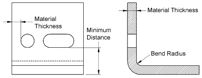
Here’s a rule of thumb: a bend radius must be equal to or greater than the thickness of the sheet metal. For example, we cannot form an 0.060” bend radius on a part made from 0.25” thick sheet metal.
Flange length
Start by talking to your manufacturing partner. (If that’s us, great!) The shop’s tooling has everything to do with flange length.
Flange length is determined by the tooling used to form a part. Generally a flange must be x4 the material thickness. A ¼” plate needs a 1” flange. Most air bending dies are shaped like a ‘V’ so if we’re bending across the top of that V, your material must be the full width of that V, and the flange must equal half of the V opening. In short, thicker material requires a wider die, and a wider die demands a longer flange.
2. Hole diameters and holes close to a bend
Like bend radii, hole diameters must equal or exceed the material’s thickness. For example, we can laser cut a 0.25” hole (or larger) from 0.25” steel, but we cannot laser cut a 0.125” hole from 0.25” steel. If a feature this small is required, the part would move from laser to a machining operation.
It’s also important to consider the location of your part’s holes. In most scenarios, any hole, notch, or cutout must be placed no closer to a bend in the material than 4x the material’s thickness. For example, if you have a 0.25” thick steel part, any hole must be at least 1” away from the bend. Holes placed too close to a bend can weaken the part, causing it to stretch.
While custom tooling does exist for achieving holes located closer to the bend, the tooling only works on materials of a certain gauge, and it can’t be used on all parts.
3. Part thickness
Sheet metal is processed in uniform sizes. A 0.25” sheet is 0.25” thick throughout the entire sheet; likewise with any other thicknesses. Therefore, a good sheet metal part must also be the same thickness throughout.
We occasionally receive drawings depicting a base with one thickness and a flange with another. Unfortunately, it’s impossible to make the part because that kind of sheet metal does not exist.
4. Inside radii
When using an air-bending press brake like ours, the part’s inside radius is determined by the bottom die opening. Unlike coined and stamped parts, which are given a specific shape, air-bent parts float inside the die where the die width creates the bend radius.
Therefore, if your part requires three different inside radii, we’ll need to use three different tools and perform three different setups. As you can imagine, this process is much longer (and more expensive) than creating a part with uniform radii.
5. Sharp inside corners
You may not even realize that your 3D modeling software has automatically turned your 90-degree bends into sharp angles, but you should know: achieving those angles is impossible! The final bend will always include a radius of at least the size of your material’s thickness.
Of course, we can still use the 3D model you provided, even with its sharp angles. Just keep in mind that the final part will not have such sharp angles and remodeling your part may be required, increasing the cost of the part.
6. U-channels
When designing u-channels, remember this rule of thumb: A u-channel’s throat must be as wide as or wider than its legs.
Wide + Short = Possible
Tall + Skinny = Impossible
Here at Baillie Fab, we can typically achieve a 6” leg using our press brake. If you need longer legs, we will need to involve our welding department. You’ll hear the same thing from most sheet metal fabrication shops, as this limitation is common when using press brakes.
7. Grain direction on brushed stainless steel parts
If you’ve requested brushed stainless steel for your part, please remember to call out the grain direction on your drawing!
The equipment in our shop accommodates sheets up to 5’ wide, with no restrictions on length. If you want a 9’ long sheet brushed lengthwise, we can easily fulfill that request! However, if you want the material brushed perpendicular to the shorter edge, be aware that the brush marks will be no longer than the material’s width—up to 5’.
8. Aluminum sheet metal fabrication
There are a unique set of rules for fabricating aluminum.
Holes
Because aluminum absorbs heat quickly, it tends to deform when too many small features are cut too closely together. So while we generally recommend holes no smaller than the material’s thickness, we increase that recommendation to 1.5x the material thickness when working with aluminum.
Bending
Aluminum tends to become brittle, which leads us to recommend an inside bend radius no smaller than 2x the material thickness; that’s double the 1:1 ratio we recommend for the inside bend radii in other materials.
9. The K factor
What is the K factor? It’s the ratio between your material’s thickness and its neutral axis. You might say that the K factor denotes an invisible line where a material’s compression and tension meet, allowing you to compensate for compression or elongation.
Like bending your arm at the elbow, bending a workpiece compresses the material on the inside of the bend while stretching the material on the outside of the bend. Knowing your material’s K factor allows us to optimize bend locations to minimize sheet elongation, increase part accuracy, and produce the highest-quality parts possible.
The Baillie Fab team will always handle any K factor calculations; nothing for you to do here! However, remaining aware of this ratio can help you better understand why we make certain recommendations.
Design for Manufacturing = Exceptional Sheet Metal Fabrication
Parts that haven’t been designed for manufacturing are highly likely to require changes before sheet metal fabrication begins, which can be a time-consuming and costly process.
But you can avoid those frustrations by paying close attention to DFM recommendations. With the tips we shared in this list, you’ll quickly see your spending shrink, your lead times compress, and your part quality achieve new levels of excellence!
Request your next sheet metal fabrication quote on our website’s secure portal, and our software will automatically identify DFM issues so we can offer our recommendations early!


